The Guitar Gallery Forums - The Guitar Legacy of Matsumoku

Q&A, discussion, and information for the labels covered by The Guitar Gallery (Specifically and exclusively guitars made by Matsumoku up to 1987)
It is currently Tue 14 May 2024 06:11 AM

All times are UTC - 5 hours


Post new topic Reply to topic
 [ 9 posts ] 
Author Message
PostPosted: Thu 05 Aug 2010 01:24 AM 
Offline
Gallery Friend

Joined: Thu 05 Aug 2010 01:02 AM
Posts: 5
I have this 81 SB1000 that has needed a new pickup and preamp for quite some time. I finally saw that they had been reissued and was able to purchase a replacement pickup and preamp from Barney Tower at Dana B. Goods. I have the schematic, and everything seems connected except the pickup and the two 9V battery clips. But.....Maybe I am a dolt, but, looking at the diagram, I cannot make heads or tails where to connect them. It shows these wires being connected to certain numbers on what is labelled "Black Box", but I don't see these things on the circuit board. Here are some photos of the schematic, front and back of the circuit board, and the wires coming from the pickup. Any help you could give me would greatly appreciated. Would love to hear this guitar sing again!! My apologies if this is as obvious as the nose on my face, but....I am confused.

Image

Image

Image

Image

Image


Last edited by EquineGuest on Thu 05 Aug 2010 08:19 PM, edited 1 time in total.

Top
 Profile  
Reply with quote  
PostPosted: Thu 05 Aug 2010 02:25 AM 
Offline
Virtuoso
User avatar

Joined: Sat 25 Mar 2006 09:25 PM
Posts: 3198
Location: Grand Absurdity, TX
Welcome!
So, the circuit (Black Box) and pickup came from the same place and are not original, correct?
The numbers in the schematic should correspond to the wires in the big connector. Are there any numbers on the board by the connections?
Possibly a dot by one end? This could be pin 1. Are you putting the wires in the connector or did they come that way?
My concern is the last 3 wires seem out of place.


Top
 Profile  
Reply with quote  
PostPosted: Thu 05 Aug 2010 03:39 AM 
Offline
Gallery Friend

Joined: Thu 05 Aug 2010 01:02 AM
Posts: 5
Thank you for the welcome, and your post!


Yes, they came from the same place, and are not original. They are from the reissue SB 1000's being produced now.

I purchased them here.

http://www.ariausa.com/support/support.html


It came pre-wired, (potentiometers-1 vol and 1 tone, plus the large multi position pot, jack and switch). I did not connect any of the current wires to the board. The pickup and battery clips are all that is left to be connected. There are no numbers on the circuit board, just the designation S1 for the small connector, and S2 for the large connector. I do not see a dot on one end, although there is what looks like a scratch (horizontal line on one end, you can see it in the top photo of the circuit board).


Top
 Profile  
Reply with quote  
PostPosted: Thu 05 Aug 2010 01:35 PM 
Offline
Virtuoso
User avatar

Joined: Sat 25 Mar 2006 09:25 PM
Posts: 3198
Location: Grand Absurdity, TX
Exactly as I expected. To me, the schematic doesn't coincide with the circuit.
From the schematic, I'd expect a blue wire (3) in the empty slot of the big connector.
I'd also expect the last 3 wires to be blue, brown and red rather than red, black and blue.
Give Barney a shout. I'll bet he can shed some light on it.


Top
 Profile  
Reply with quote  
PostPosted: Thu 05 Aug 2010 07:53 PM 
Offline
Gallery Friend

Joined: Thu 05 Aug 2010 01:02 AM
Posts: 5
I have been trying to get a reply, but no luck. So, kind of on my own it seems.


Top
 Profile  
Reply with quote  
PostPosted: Thu 05 Aug 2010 08:00 PM 
Offline
Gallery Friend

Joined: Thu 05 Aug 2010 01:02 AM
Posts: 5
Is it possible that this wiring diagram is for an original early SB1000, and not the current reissues. This is the one that Barney sent to me. Any ideas on where to get a current wiring diagram? Or a photo of the inside of the cavity of one?


Top
 Profile  
Reply with quote  
PostPosted: Fri 06 Aug 2010 03:29 PM 
Offline
Virtuoso
User avatar

Joined: Tue 09 May 2006 11:57 AM
Posts: 651
Location: The Heartland
Hello,
Yes, the schematic doesn't seem to point out where the pick-up and 18 VDC connect. In my case I didn't actually have to replace the pre-amp, so it was a pretty easy fix.

I will take some pics and fix them up with arrows and such-should be able to help you out. :D

Will be leaving for the weekend, but will try to post before I do.

Hang in there, It won't be hard, I promise !

_g


Top
 Profile  
Reply with quote  
PostPosted: Fri 06 Aug 2010 09:33 PM 
Offline
Virtuoso
User avatar

Joined: Tue 09 May 2006 11:57 AM
Posts: 651
Location: The Heartland
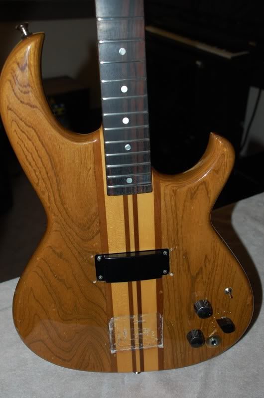
Ok, I had a look at both my SB1000 ( still with original pre-amp set up,) as well as the new wiring harness and pre-amp that i got from Aria USA. ( and as it turns out, didn't really need)

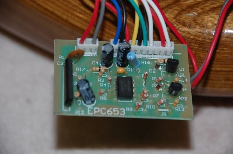
There are a few minor differences, it looks like they have probably simplified the circuit some ( ie. no more mystery black box wrapped in tape for the LED)

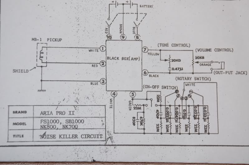
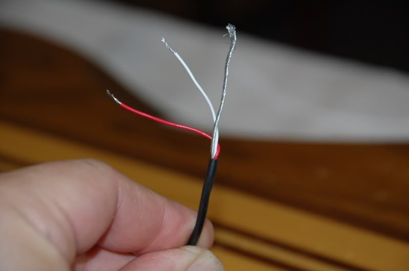
At any rate, try this for the pick-up connections.The toggle switch should only have 2 tabs open- the white wire from the pick up goes to the center middle, the red wire goes to the center outside. ( The braided shield should be grounded to the back of the volume pot) Simple enough, right ? :D

Things get a little hairier with the battery hook-up, but here goes.........

From the 2 9V battery leads, take the red wire from battery#1 and connect it to the black wire from battery #2, putting the batteries in series for your 18VDC.( just like a flashlight)

Now take the remaining leads (1 ea red and black from the 2 batteries.)

Your output jack should already have 4 wires connected to it. It also functions as an on/off switch for the batteries. MY BEST GUESS for this ( since this is arranged slightly differently from my '84 SB)is that the red lead from the batteries should go to the tab located between the red and white wires on the jack., and the black lead should go to the tab in the opposite corner , next to the blue wire.

I would STRONGLY suggest getting pair of test leads and trying out the hook up before you commit to soldering anything. If you're not comfortable with soldering, it would probably be well worth it to throw a tech a few bucks to do it for you. :)

Hopefully this helps. Let us know how it turns out.

Cheers,
Gribb


Top
 Profile  
Reply with quote  
PostPosted: Mon 09 Aug 2010 04:06 AM 
Offline
Gallery Friend

Joined: Thu 05 Aug 2010 01:02 AM
Posts: 5
Great! I will give this a shot, and let you know how it all works out. Looks as if the schematic is for the original SB series, and not the newer circuit. Thank you so much!


Top
 Profile  
Reply with quote  
Display posts from previous:  Sort by  
Post new topic Reply to topic  [ 9 posts ] 

All times are UTC - 5 hours


Who is online

Users browsing this forum: No registered users and 2 guests


You cannot post new topics in this forum
You cannot reply to topics in this forum
You cannot edit your posts in this forum
You cannot delete your posts in this forum
You cannot post attachments in this forum

Search for:
Jump to:  
Powered by phpBB® Forum Software © phpBB Group